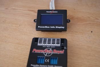


This powerbox is currently the top of the range unit produced by Powerbox-Systems (with the exception of the same version which includes Spektrum technology) and has been for some time THE unit used for large scale models, irregardless of their type.When we open the box, the first thing that we see is a beatifully designed powerbox (beatifull for an aeromodeller of course!).
It has 7 channels, 5 of them have four exits each, each one of them can be programmed independantly, as well as another 2 channels with 3 exits each (non programmable). The unit has everything duplicated, with two receivers, two batteries, and as explained by our friends at Powerbox-Systems, the unit actually holds two, identical powerboxes, so if one where to fail, the second one can still take over.
It also includes a screen that can be installed in the model, which is used for the programming, and also the status of the battery or receiver signal.
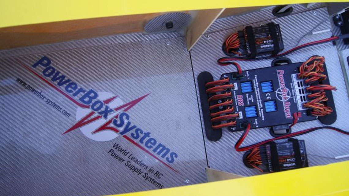
Its install is very simple, with just four screws using the same system as servos (rubber gromment with brass eyelets)
Even though it is designed for use with two receivers, it is also possible to use just one, simply connecting it to the receiver port 1.
We can also choose if we wish for the servos to run on 5,9v or 7,4v (such as for new HV servos). Irregardless of this, the receiver will only ever receive 5,9v as required.
The programming of the Royal RRS is the same as the Champions RRS, only with 5 programmable channels as opposed to 3. The programming would therefore be as follows:
The first phase of teaching the powerbox the throws of the transmitter is completed as follows:
-We move the first dial on the adjuster board to “A” and the second dial to “Reset”
-Now we press the buttons “+” and “-” at the same time. (the yellow and red LED will light up on the adjuster board),
-With the transmitter stick in the centre, we press the “+” button (so that the powerbox memorises the centre position)
-Holding the transmitter stick at full throw, we press again the “+” button (so the powerbox memorises the full throw position)
-We do the same for the oposite full throw, again pressing “+”. (so the powerbox memorises the opposite full throw position)
-When we press the “+” button for the third time, the powerbox accepts that you have told it the three programming spaces (full left, centre and full right) and the yellow LED will turn off. To save the positions for the servo, move the second dial to “Save” and press “+”, with this the red LED will turn off and the settings have been saved.
The second phase of programming the servos for your model:
-Connect ONLY the first servo and programme it as normal (using transmitter sub trim and end point adjustments).
If you wished to do so, you could also programme it with the powerbox using the same process as the other servos, as follows..
-Connect the second servo, however leave one of the ball links disconnected. Select on the first dial “A” and the second dial servo number “2”. To programme the centre, leave the transmitter stick in the centre and adjust the servo centre with the “+” and “-” keys. To assure that it is correctly centred, you should be able to put in the bolt for the loose ball link easily.
-To programme the full throw, do exactly the same, holding the transmitter stick on full and adjust the servo position with the “+” and “-” keys, repeating the test that you can easily put the bolt through the ball link.
-Repeat the same process for the opposite full throw.
-As soon as you make one change, the red LED lights up, to indicate that a change has been made but has not yet been saved. To save the changes, move the second dial to “Save” and press the “+” button. the red LED will go out because the changes have now been saved, and your servos are sincronised correctly.
Now we simply repeat the same process as many times as necessary until we have all servos programmed.
During the programming we can see on the screen what adjustment we are making. “C” is the center of the servo (sub-trim) and “L” & “R” are Left and Right (end points)
In the bottom half of the screen, you can also see:
“Channel” – This is to indicate the channel that we are adjusting (A. B, C, D or E)
“Servo” -This is to indicate which servo of that channel we are adjusting (servo 1, 2, 3 or 4)
“Current” – The current being used on that servo (this can be used to assure that the adjustments have been made correctly, and therefore the servo is not in a stalled position (which would increase power consumption)
“Saved” – This indicates if the changes have been saved. If saved there is a “tick”
“Init” – This indicates that you have made a modification to this servo (since turning the Royal on)
The Royal also has an option called “Black Box” which can be accessed by pressing momentarily both battery muttons on the swith (buttons I and II) and indicates
“Time” – how long the Royal has been turned on for
“Consumption” – How many mAh has been used from each of the batteries in this time since the unit has been on
“Min Voltage” – minimum voltage from each of the batteries
“Max Current” – maximum current drawn in A of each battery
“Online RX I y II” – This is the satus of the two receivers. Both should be at 100%, if not there might be a problem with the conection or signal
“Switches I->2 or 2->1” – This is the number of times that the Royal has had to switch from receiver one to reveiver two (or vice versa) due to a weak signal or receiver bad connection. This should always show 0, if not look into receiver placement, binding and all wire connections.
This is the normal screen that we see when we turn the Royal on. It shows the status of each of the two batteries, both as a graphic, as well as voltage. It also shows the exit voltage given by each of the regulators, and the mAh used from each battery.
